Lithium Battery Module Fully Automatic Assembly Line
Lithium battery module fully automatic assembly line is mainly used in the production of new energy lithium battery modules, square battery modules, energy storage battery modules, power battery modules and pack welding assembly, etc.
Battery Pack Assembly Line
Streamline your battery production process with our cutting-edge Battery Pack Assembly Line. Harnessing advanced technology, our fully automatic assembly line delivers superior performance and reliability. Stay ahead in the competitive battery industry while increasing efficiency and profitability. Invest in automation for faster turnaround times and consistent quality.
Automated Battery Cell Assembling Design Requirements
1.1、Automated Battery Cell Assembling Technical parameter:
(1)Equipment capacity: ≥10PPM;
(2)The final excellent rate is ≥99.8% (only the bad products caused by the equipment);
(3)Equipment failure rate ≤ 2%;
(4)Compatible with a variety of size module specifications, quick change. Laser output power stability (fluctuation) ≤±1%, the focal length of the galvanometer can be digitally displayed and adjusted, the range is -5.0~+5.0mm, and the adjustment accuracy is ≤0.5mm;
(5)The welding track is edited by welding software, the welding process is automated, the parameters can be modified, and the operation and modification authority can be set
1.2、Flow Chart:

Tentative process flow, subject to actual requirements
Program Layout
2.1 Program Renderings:

2.2 Layout Size:

Back layout size(L*W*H):19500mm*9000mm*3200mm
Front layout size(L*W*H):13000mm*6000mm*2300mm
Function Module Introduction
3.1 Cleaning Gluing Station
3.1.1 Equipment description:

Internal structure diagram of cell cleaning and gluing
Introduction of cleaning and gluing station: 1. After the worker places the battery cell on the feeding conveyor belt, the equipment can automatically complete the cleaning and gluing; 2. Equipment beat: 12PPM;
3.1.2 Equipment parameters:
|
Name |
Parameters |
|
Power supply |
AC220V/50HZ |
|
Air supply |
0.5-0.7Mpa |
|
Size |
L2600mm*W1250mm*H1800mm |
|
Working temperature |
5-40℃ |
|
cleaning range |
X/Y(mm):300/300mm |
|
gluing range |
X/Y(mm):300/300mm |
|
Moving speed |
X/Y/Z(mm/set):300mm |
|
repeat accuracy |
±0.02mm |
|
Weight |
About 650KG |
|
glue ratio |
1:1 |
|
AB mix |
Dynamic mixing |
|
gluing accuracy |
0.02g,The error ratio does not exceed ±5% |
|
Robot system |
BORUNTE 4 axis Robot |
|
Operating mode |
point-to-point/continuous line segment |
|
Gluing system |
HY |
|
Control system |
HY |
|
Pneumatic Components |
Airtac |
|
servo motor |
Panasonic Servo System |
|
Photoelectric Sensors |
Omron |
|
Power |
MEAN WELL,HENGFU |
|
Ball screw |
TBI |
|
Linear Guides |
HIWIN |
|
Frame |
Fangtong welding mechanism、countertop soldering iron block、gantry milling |
|
sheet metal |
Sheet metal fully enclosed structure, transparent window |
Contact us for more information of automatic assembly line.
3.2 Stacking Rotary Tables

3.2.1 Description of the Action Flow:
1. Action process: The stacking robot unloads and unloads materials from the gluing equipment conveyor line, and performs stacking operations in the serial-parallel sequence of the module recipes. This stacking method can flexibly accommodate module combinations with different recipes in series-parallel sequences. The stacking sequence is from bottom to top, and the cells and insulating plates are alternated, from the 1st hand cell to the 1st hand insulating plate, and then to the last hand 1 cell. During the stacking process, a downward pressing and beating mechanism is simultaneously pre-pressed and fixed.
2. The gripper is controlled by the robot to control the gripping mechanism, and the gripper is designed with photoelectric induction cells in place. The module stacking platform adopts a fixed-slope dual-station design. Each station contains dual clamps, which can place two cells at the same time. When the A station is stacking, the B station synchronously performs the moving work before extrusion, and the double station alternates, so as to improve the efficiency of stacking and moving.

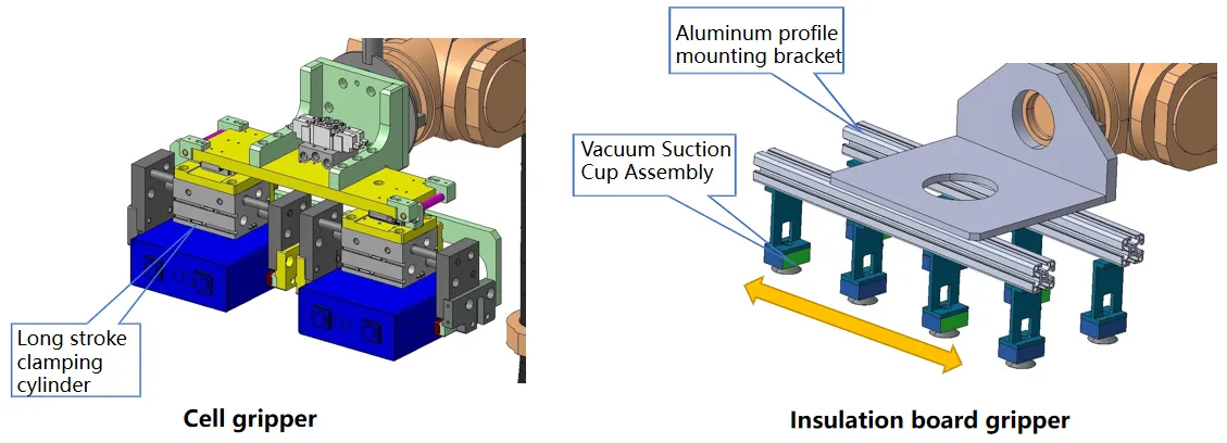
3.2.2 Changeover Strategy Explained:
1. Change the cell gripper: choose a long-stroke clamping cylinder, which can be automatically compatible with different types of cells when changing;
2. Changing the gripper of the insulating plate: the vacuum suction cup assembly is installed on the aluminum profile, and the distance between the suction cups can be adjusted manually according to the width of the insulating plate when changing the model.
3. Electrical program: According to the serial-parallel stacking sequence of compatible modules, the robot performs the stacking operation according to the preset robot stacking sequence program. Before changing the model, the stacking program of the model-changing product is transferred.
3.2.3 Changeover Strategy Explained:

3.3 Function module introduction
3.3.1 Extrusion station: Double-row module process

1. The handling robot transports the single-row stacks 1 and 2 respectively from the stacking turntable to the extrusion table sliding table, and the sliding table slides to the manual extrusion position; 2. Manually install the middle partition board (manual cleaning and gluing), end insulation board (manual cleaning and gluing), and end plates (manual cleaning and gluing), and then press the button to install the steel cable ties.
3.3.2 Extrusion station:

3.3.3 Extrusion station: Equipment flow description:
1. Place the glued cells by the handling robot to the discharge position of the sliding table, and the sliding table automatically slides to the manual extrusion position;
2. Manually attach both ends to the end plate, install the side rails, first press the width direction extrusion button to make the length direction of the module horizontal; then press the extrusion start button, the cylinder drives the top plate to extrude the cell, When it reaches the set length, it stops, inserts the steel belt, punches the plastic steel belt, and rives the screw;
3. After the installation is completed, press the open button, squeeze the cylinder to retract, and then press the slide button, the installed module slides to the discharge position again, and the robot grabs it to the stationary trolley.

3.3.4 Extrusion station: Changeover Strategy Explained:
Extrusion Tooling Changeover Instructions
1. Change of handling gripper: Servo + screw clamping mechanism is adopted, and the electrical program can be switched with one key during model change;
2. Extrusion table change: choose a long-stroke clamping cylinder, which can be automatically compatible with different types of batteries when changing;
3. Robot program: According to the size of the compatible module, the robot will follow the preset robot handling program. Before changing the model, transfer the handling program of the replacement product.

3.4 Introduction of safety fence:

1. The design, manufacture and control of the safety fence comply with the relevant national regulations on production safety to ensure the safety of the production process.
2. Protective fences, fences, safety nets and other facilities are set up in places where human or machine damage may occur, and necessary interlocking protection is carried out. The safety door lock should be interlocked with the system. The safety door is self-locking and cannot be opened when the production line is working.
3. Entering the security door operation process: apply for entry - the robot and other equipment are parked in a safe position - the security door is opened - enter the security door.
4. Operation process for resuming production: go out of the security door – confirm that there is no one in the equipment area – close the security door, enter the recovery password, and the security door is self-locking – the equipment is operating normally.
3.5 Insulation withstand voltage test station:
The insulation test before welding is conducted by pressing all probes through the overall test mechanism, and then switching between the cell and the cell through the relay. Insulation test between shell and shell; Test procedure: all positive poles in series, all negative poles in series after the insulation test between the two, and then all positive.
Insulation test between pole series and housing, insulation test between all negative pole series and housing.

3.6 Insulation withstand voltage test station:detailed description of the equipment:
1. Operation process: the tray is lifted and positioned, the shell probe is pressed to the end plate or the side plate, and the positive probe relays of all cells are closed, so there is insulation between the positive electrode of the cell and the shell; the positive electrode of all cells is Divide into two groups, an odd-numbered group and an even-numbered group, and test the insulation between the positive electrodes.
2. Model replacement strategy: According to the arrangement of the cells corresponding to the pallet arrangement, establish a coordinate system for the coordinates of the formula skipping step. Before changing the model, call up the test jump coordinate program, carry out the first piece test OK, and proceed to the production mode after the model changing.

3.7 Pole photo station:

Introduction of pole photo station:
1. This station first takes the MARK point of the module, and then takes each pole;
2. Then bind the photo information with the module code and send it to the laser welding station.
3.7.1 Equipment details:
1. The equipment is mainly composed of three-dimensional table, CCD and light source, rack cover, automatic code scanning gun;
2. Action process: After the module is lifted and transferred to the pole photographing station through the double-speed chain, the 3D stage identifies the module model according to the barcode captured by the automatic code scanning gun. Find the position, and then shoot 2 MARK points on the end plate. After the positioning is completed, it will form a coordinate system, which will be sent to the cleaning station and the welding station through the PLC, and the tooling tray will flow to the next station after descending.

1. The three-dimensional stage drives the camera and ranging sensor to take pictures and ranging, which can realize false capture, diameter, and straightness.
2. Use template matching to roughly locate the product position, and then use a circular measuring tool to determine the center of the two circles inside and outside the pole ring for welding positioning.
3. Working method: word shooting statically completes measurement and positioning, compatible with copper and aluminum materials.
3.8 Pole cleaning station

Introduction of pole cleaning station: This station uses robots and lasers to clean the poles;
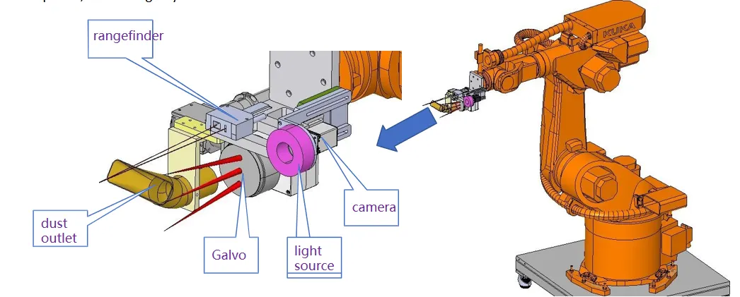
3.8.1 Equipment details:
1. The equipment is mainly composed of six major parts: robot, CCD and light source, hood, automatic code scanning gun, rangefinder, and galvanometer;
2. Action process: After the module is lifted and transferred to the laser cleaning station through the double-speed chain, the robot recognizes the module model according to the barcode captured by the automatic code scanning gun, and the robot program automatically adjusts the height and then performs distance measurement and MARK point photography. After the photographing is completed, each pole is automatically cleaned according to the coordinates sent by the pole photographing station. After the cleaning is completed, the tooling tray descends and flows to the next station.
3.9 Laser welding station

Laser welding station introduction:
1. This station first takes the MARK point of the module, and then calculates the offset of each pole based on the data sent by the photographing station;
2. All busbar welding positions are measured for distance, and then laser welding is performed.
3.9.1 Equipment details:
1. The equipment is mainly composed of six parts: three-dimensional table, galvanometer, CCD and light source, rack hood, automatic code scanning gun, and rangefinder;
2. Action process: After the module is lifted and transferred to the laser welding station through the double-speed chain, the three-dimensional table identifies the module model according to the barcode captured by the automatic code scanning gun, and the three-dimensional table program automatically adjusts the height and then performs ranging and MARK points. Take pictures. After the pictures are taken, the busbar welding is automatically carried out according to the coordinates sent by the pole photographing station. After the welding is completed, the tooling tray descends and flows to the next station.

3.10 Cantilever crane mechanism
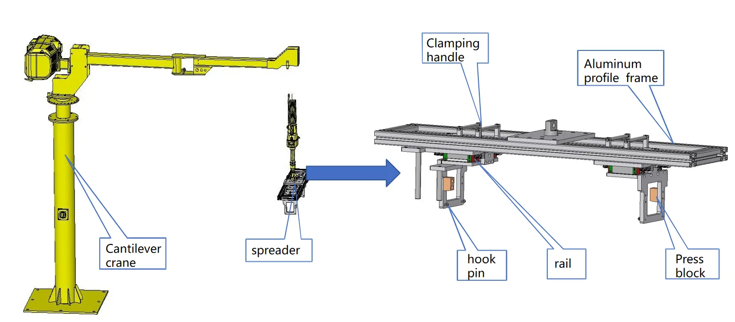
3.10.1 Explanation of Changeover Strategies:
1、Spreader replacement strategy description:
1. Hook pin replacement: Hook pin and connecting plate need to be manually replaced according to different models of modules;
2. Change in the length direction: the length direction is compatible, and the connection block can be adjusted directly on the aluminum profile manually.

3.10.2 Cantilever crane mechanism:

3.11 Tray introduction

3.11.1 Pallet Introduction: Changeover Strategy Explained
1. Pallet replacement strategy description:
1. Width direction type change: manually change the position of the side stop (the bottom plate of the tray will be prefabricated with different types of holes);
2. Change in length direction: manually replace the position of the card slot of the front block directly.

3.12 FPC welding workstation:
1. The equipment is mainly composed of five parts: three-dimensional table, galvanometer, CCD and light source, rack hood, and rangefinder;
2. This equipment is used for offline manual welding of FPC boards. FPC and bar positioning tooling are provided by customers.

Industry Application
Lithium battery module fully automatic assembly line is mainly used in the production of new energy lithium battery modules, Prismatic battery modules, energy storage battery modules, power battery modules and pack welding assembly, etc.
Streamline Your Battery Production Process
Unlock Efficiency and Boost Productivity
Are you tired of the time-consuming and labor-intensive process of assembling battery packs? Look no further than our cutting-edge Battery Pack Assembly Line. Designed to revolutionize your production process, this fully automatic assembly line will streamline your operations, saving you valuable time and resources.
With our Battery Pack Assembly Line, you can say goodbye to tedious manual labor and hello to increased efficiency. By automating the assembly process, our state-of-the-art machinery eliminates human error, ensuring consistent and precise results. Experience a significant reduction in production time while maintaining the highest standards of quality.
Advanced Technology for Superior Performance
Harness the Power of Innovation
Our Battery Pack Assembly Line integrates the latest advancements in technology to deliver superior performance and reliability. Each component of the assembly line has been meticulously engineered to provide exceptional results, surpassing industry standards.
Featuring advanced robotics, intelligent control systems, and precision engineering, our assembly line maximizes accuracy and speed. It seamlessly handles various battery pack configurations, accommodating diverse product specifications. From small-scale to large-scale production, our flexible and adaptable system empowers you to meet market demands efficiently.
Elevate Your Competitive Edge
Stay Ahead in the Evolving Battery Industry
In today's fast-paced and competitive battery industry, staying ahead of the curve is essential. By investing in our Battery Pack Assembly Line, you gain a significant advantage over your competitors. Embrace innovation, enhance your production capabilities, and position yourself as a leader in the market.
With the ability to scale your production output and maintain consistent quality, our assembly line enables you to meet growing customer demands while reducing costs. Increase your profitability and customer satisfaction with faster turnaround times and superior battery pack assembly.